Thursday, 18 May 2017

TURBINE FLOW METER

TURBINE FLOW METER

Turbine flowmeters use the mechanical energy of the fluid to rotate a “pinwheel” (rotor) in the flow stream. Blades on the rotor are angled to transform energy from the flow stream into rotational energy. The rotor shaft spins on bearings. When the fluid moves faster, the rotor spins proportionally faster.

Shaft rotation can be sensed mechanically or by detecting the movement of the blades. Blade movement is often detected magnetically, with each blade or embedded piece of metal generating a pulse. Turbine flowmeter sensors are typically located external to the flowing stream to avoid material of construction constraints that would result if wetted sensors were used. When the fluid moves faster, more pulses are generated. The transmitter processes the pulse signal to determine the flow of the fluid. Transmitters and sensing systems are available to sense flow in both the forward and reverse flow directions

LASER LEVEL TRANSMITTER WORKING PRINCIPLE

LASER LEVEL TRANSMITTER
The laser level transmitter either uses triangulation, time of flight or confocal chromatic working principle
Triangulation
One method for accurately measuring the distance to targets is through the use of laser triangulation sensors. They are so named because the sensor enclosure, the emitted laser and the reflected laser light form a triangle.
The laser beam is projected from the instrument and is reflected from a target surface to a collection lens. This lens is typically located adjacent to the laser emitter. The camera views the measurement range from an angle that varies from 45 to 65 degrees at the centre of the measurement range, depending on the particular model.
Time of flight

This technique uses the time light takes to travel to a target and back, but the time for a single round trip is not measured directly. Instead, the strength of the laser is rapidly varied to produce a signal that changes over time. The time delay is indirectly measured by comparing the signal from the laser with the delayed signal returning from the target.
Confocal chromatic:
This uses use a white light source to accurately measure the distance to surfaces. The essence of our confocal chromatic imaging principle is the accurate detection of colours from light that is reflected back from target surfaces. The white light is focused onto the target surface by a multi-lens optical system. These lenses disperse the light into monochromatic stages (colours) along the measurement axis. A specific distance to the target is assigned to each colour’s wavelength in a factory calibration. Only the wavelength which is exactly focused on the target is used for the measurement. This light reflected from the target surface is transmitted from the probe, through a confocal aperture and onto a spectrometer which detects and processes the spectral changes and calculates distances. These distance measurements are transmitted at high speed via Ethernet communications protocol.

Some of the laser LT are below


Advantages of using DELTA V DCS

Instrument Loop Diagram

SMP of a control valve

Bently Nevada VMS

Level supression and elevation of DP type level transmitter

Wednesday, 22 February 2017

OIL IN WATER ANALYZER


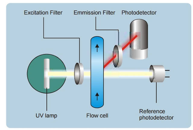
The measuring principle is based on fluorescence: when lighted at a specific wavelength (excitation), some chemicals re-emit light (emission) at another longer wavelength according to Beer Lambert law. 

Very few chemicals are fluorescent and give a highly selective measurement. The emission light is detected by a high sensitivity photo multiplier to detect very low concentrations from a few ppb(particles per billion). The excitation light is controlled by a detector to compensate any variation of the source.The most generally used OIW analyzers are Forbes Marshal and AWA 

BS&W ANALYZER(Basic Sediment And Water) or water in oil analyzer

Principal of operation ‘Oscillator Load Pull’  analyzers (BS&W) achieve superior performance by utilizing microwave oscillator load pull. Load pull is the term given to describe the frequency change of an unbuffered oscillator as its output load varies. Circuit components and the external load impedance determine an unbuffered oscillator's frequency. The permittivity of the materials in the measurement section, through which the microwaves propagate, determine the output load. The measurement section consists of a small solid rod mounted inside a larger diameter pipe, as shown in Figure 1. One end of the rod is connected to an unbuffered oscillator and the other end connects to the center of a welded "shorting" plug. The center rod is covered by a hard plastic sheath to prevent direct contact between the metal rod and conductive water-oil emulsions. Electrically this pipe, rod, and sheath combination is a coaxial transmission line, terminating into a short circuit. The fluids flow through the measurement section via the connections that mount perpendicular to the run section, one at each end. The microwave signal travels the length of the pipe twice; down the pipe from the oscillator, then reflects at the shorting plug and traverses back to the oscillator module


kishore karuppaswamy


The permittivity of the emulsion changes as the percentage of water in the total fluid changes. The permittivity of the emulsion is comprised of two parts - the dielectric constant and the loss. The relative dielectric constant of oil is 2.2 and of water is about 70. The loss is determined primarily by the salt content of the water. Accurate measurement of the water salinity and proper input to the electronics unit is essential for best accuracy of the Phase Dynamics Full Range WaterHydrocarbon Analyzer. In summary, the permittivity of the oil-water emulsion in the measurement section provides a complex impedance, or load. The load acts directly upon the unbuffered oscillator to force a predictable, repeatable, and precise change in frequency. This frequency is proportional to the water content of the emulsion. Temperature and loss also affect the frequency; both are used for compensation to calculate the correct water content. The microprocessor uses the measured frequency to calculate and update the water content each second.The best make of BSW analyzer is from phase dynamics


"In OLP,oscillators frequency changes when its load impedance changes.Here the oscillator operates in microwave frequency and is propageted through the measurement section which is the load and the measurement section is dipped in liquids of permittivities or the dielectric constant of the emulsion.Thus as the impedance changes due to a change in percentage of water in oil,the frequency changes.The frequency and the fluid temperature are measured and gives a value in water content"

REYNOLDS NUMBER

Calibration-and-initialization-of-wet-leg-impulse-tube-rosemount-3051cd-series-lt

Calibration-and-initialization-of-electronic-remote-seal-level-transmitter-rosemount-3051ers

CONTROL VALVES

CALIBRATION OF GWR LEVEL TRANSMITTER

PRESSURE UNITS CONVERSION

DATA COMMUNICATION PROTOCOL

TIPS AND TRICKS IN FIELD INSTRUMENTATION

LEVEL MEASUREMENT USING PRESSURE GAUGE

FREE NOVELS

Free Instrumentation Text Books

Instrument gland sizes for cables

LRV and URV setting of differential pressure transmitter for level measurement

Instrument Measurement Principles continuation......


to be continued....